Friction is not just a design parameter in large water transmission systems. It directly influences pipe diameter, pump head, motor sizing, energy cost, delivered flow, and EPC performance guarantees. GRP pipes are delicate materials that ensure a perfect performance under changing hydraulic stress, but the friction values are founded on real data, not just assumptions or catalog data.
At LineCore Pipes Group, we provide a smart design for GRP pipes which includes product selection, installation quality, commissioning checks, and long-term operation to help you make your piping decisions reliably.
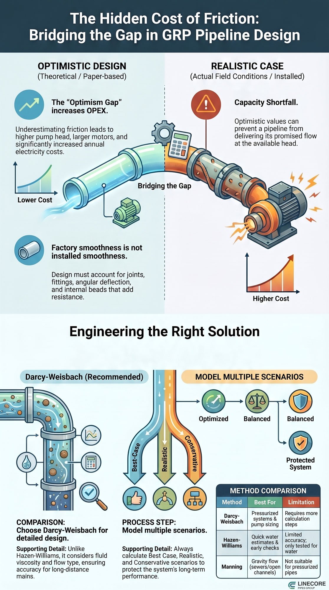
GRP pipeline friction factor cost infographic (source: Pipelinecoregroup.com)
What Is Friction Factor in a Transmission Pipeline?
A simple idea that drives real engineering decisions. The friction factor shows how much energy water loses as it flows through a pipe. In a pumped transmission line, that loss does not disappear. It turns into extra pump head and higher electricity use.
This one parameter shapes several design decisions. A higher friction rate requires more pumping energy, and this is where pump head increases. That leads to larger pump motors and higher capital costs. It can also push engineers to select a bigger pipe diameter to reduce resistance.
Friction Counts per Moment!
Friction also influences daily operation. If losses are higher than expected, the system power consumption goes higher per hour. Thus, this adds to annual electricity cost and total lifecycle cost.
It can also reduce the actual flow delivered to the end user. In some cases, the pipeline cannot meet its design capacity unless pumps run at higher speed or for longer hours.
What Risk Does Come from Friction Loss?
There is also a contract risk. In EPC projects, flow and efficiency are what show performance guarantees. If friction is too low in the design, the system may not hit those targeted points. This may show disruptions or further upgrades in the future.
- Ending Tip: According to edu, even small changes or mistakes in friction are hard to make up when it adds up over 20, 30, or 50 years.
Why GRP Has a Strong Hydraulic Advantage
GRP performs well when the system is designed and installed with care.
GRP is not frictionless. It is a low-headloss system when the design reflects real conditions.
The Winner Characteristics of GRP Pipes
GRP pipes have a smooth internal liner. They resist corrosion. Their initial roughness is lower than steel, ductile iron, and concrete. This reduces headloss and lowers pumping energy in long transmission lines.
The advantage is real, but not automatic. Joints, fittings, and installation quality affect the final result. Operation also plays a role over time.
| Pipe Material | General Hydraulic Character | Main Risk Over Time |
|---|---|---|
| GRP | Smooth, corrosion-resistant surface | Roughness from joints, deposits, biofilm |
| Steel | Strong structure | Corrosion and tuberculation |
| Ductile Iron | Common in water networks | Lining, ageing and wear |
| Concrete | Durable | Higher surface roughness |
| PE/PVC | Smooth polymer surface | Deformation, fittings, biofilm |
GRP starts smooth. Long-term performance depends on how the system is built and operated.
The Core Problem: Optimistic Design
Optimistic design uses best-case assumptions that rarely match real conditions.
Optimistic design happens when engineers use new-pipe smoothness values without enough allowance for installation, operation, and aging. The system looks efficient on paper, but real performance tells a different story. Below is what considered as common sources of optimism.
- One generic GRP roughness value for all suppliers
- Hazen-Williams C = 150 or higher is treated as constant
- Valves, bends, reducers, and joint losses not included
- Factory smoothness assumed equal to installed condition
- Water quality, biofilm, and sediment not considered
- Temperature and viscosity effects ignored
- No model calibration after commissioning
Each of these choices reduces calculated headloss. Together, they create a gap between design and reality.
In long pipelines, that gap becomes visible fast. Pumps work harder. Energy use rises. Flow may drop below target.
Key Point: The hidden cost does not come from GRP. It comes from treating the system as if it will always perform like a new pipe under perfect conditions.
Darcy-Weisbach vs Hazen-Williams vs Manning
This section aids you in selection the right approach, which affects accuracy and long-term results.
Hazen-Williams: Easy but Narrow
Hazen-Williams is common in water projects because it is simple to use. It does the job pretty well for quick estimates and everyday municipal systems. But here’s the catch: it was only tested with water. It doesn’t consider things like fluid viscosity, whether the flow is laminar or turbulent, or changes in temperature.
- The Use: Good for rough checks in the early stages, simple network estimates, and when you’re chatting with clients. (Source: International Associaton for Fire Safety Science)
- The Risk: It can hide serious problems if you apply it to long pipelines or high-capacity systems.
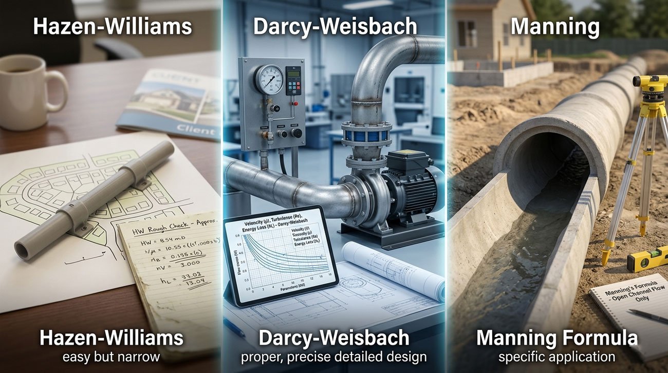
Darcy-Weisbach: The Proper Way
Darcy-Weisbach is based on real fluid mechanics. It actually considers velocity, pipe size, the type of flow, how rough the pipe is, and all the resistance that creates. It works for pretty much any fluid and any condition you’ll run into.
- When to Use It: This is what you want for proper detailed design, sizing pumps, calculating energy use, and setting solid targets in contracts.
Manning: Only for Certain Situations
Manning’s formula is mainly for open channels or pipes that aren’t running full (like sewers). It’s really not the right tool for pressurized transmission pipelines.
| Method | Best For | Limitation |
|---|---|---|
| Darcy-Weisbach | Pressurized systems | Needs calculation steps |
| Hazen-Williams | Quick water estimates | Limited accuracy |
| Manning | Gravity flow | Not for pressurized pipes |
GRP Roughness Is Not One Universal Number
There is no single friction value for GRP pipelines.
Different GRP products give different hydraulic results. Manufacturing method, liner type, joint system, and supplier data all affect performance. A single roughness value cannot represent all cases. Including essential parameters:
- Absolute roughness (k or ε)
- Darcy friction factor (f)
- Hazen-Williams coefficient (C)
- Manning coefficient (n)
- Effective in-service roughness
Each parameter describes flow resistance in a different way. They are not interchangeable.
New-Pipe vs. In-Service Roughness
Catalog values describe the pipe barrel under controlled conditions. Real systems include many added effects:
- Pipe barrel
- Joints and couplings
- Angular deflection
- Fittings and valves
- Internal steps or beads
- Air pockets
- Biofilm and sediment
- Operating conditions
These factors change the actual resistance inside the pipeline.
Practical message: The correct design basis is not “GRP is smooth.” It is a defined hydraulic value for a specific product, system, and operating condition.
The Hidden Cost: Energy and Pumping OPEX
Small friction errors can turn into large energy costs.
Pump power depends on flow and total head. As noted in ScienceDirect, when friction head is too low in the design, the pump must add more energy to move the same flow. This increases power demand and operating cost. In some cases, the system cannot reach the required flow at the available head.
Pump power relation:
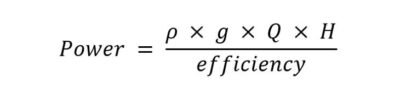
Q = flow rate
H = total head
Efficiency = pump and motor efficiency
Friction head is part of H
Even a small increase in head can raise energy use over time. In long transmission lines, a few extra meters of head can lead to very high electricity costs over the project life.
Check the chart below, which represents the relation between energy costs per year and years of operations, whether in real cases, optimistic assumptions, or conservative cases.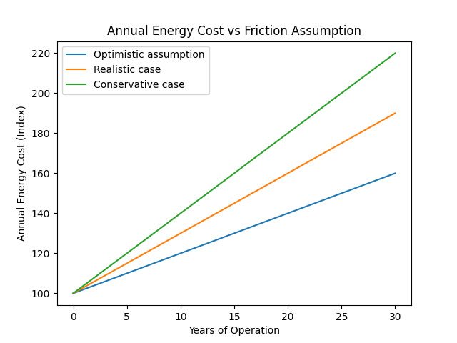
The chart shows how friction assumptions change energy costs over time. The optimistic case starts low but rises. The realistic case shows expected operation. The conservative case has the highest cost. The gap grows each year. Even small friction differences lead to big energy costs over the pipeline’s life.
Capacity Shortfall: When the Pipeline Cannot Deliver the Promised Flow
Lower delivered flow is a direct operational risk.
Optimistic friction values can lead to under-design. The pipe may be installed as planned, but the system may not deliver the required flow at the available pump head. The issue appears during operation, not during construction.
- Client dissatisfaction when targets are not met
- Pumps run at higher speeds or for longer hours
- Loss of reserve capacity in peak demand
- Need for pump upgrade or system modification
- Higher energy use than planned
- Disputes over EPC performance guarantees
The system then shifts from a design problem to an operational burden. Operators must be prepared for the gap between expected and actual performance.
- Practical point: A pipeline that looks cost-effective at the CAPEX stage can become expensive when higher OPEX continues for decades. (Source: LinkedIn)
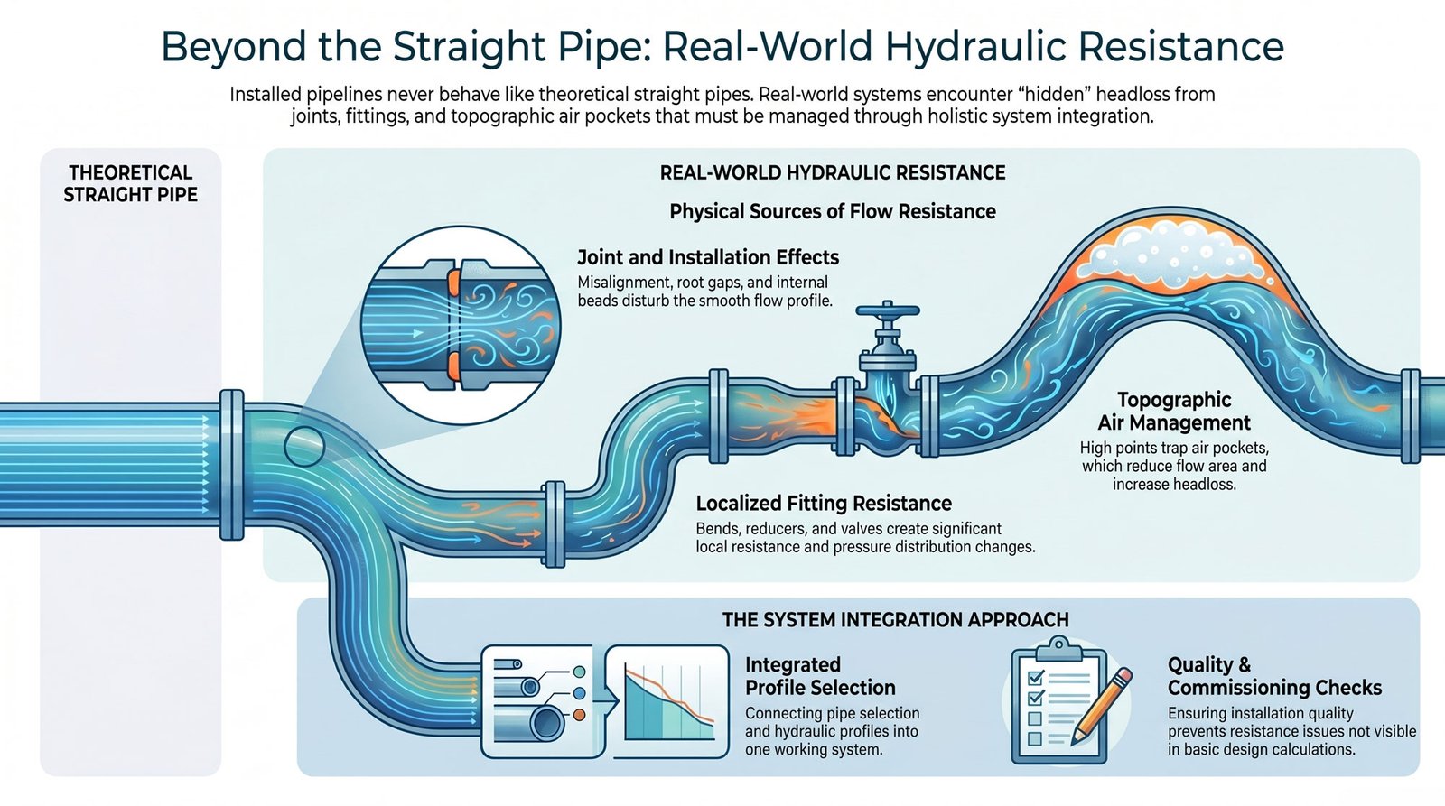
Joint, Fitting, and Installation Losses
The installed pipeline never behaves like a perfect straight pipe.
Real systems include many elements that add resistance. These losses are often small in isolation, but they build up along the line and affect total head.
1. Joint Effects
Couplings and butt-and-wrap joints can introduce small internal steps. Based on an article in Scribd, misalignment, root gaps, or internal beads can disturb flow. These details change the smooth profile assumed in design.
2. Fitting and Valve Losses
Bends, reducers, tees, and valves all create local resistance. Entrances and exits also add loss. Each component may have its own effect on velocity and pressure distribution along the pipeline.
3. Topography and Air Management
High points in the profile can trap air. Air pockets reduce effective flow area and increase resistance. Poor profile control can add hidden headloss that is not visible in basic calculations.
- EPC Perspective: This is where system integration matters. Linecore Pipes Group makes all pipe selections, hydraulic profiles, fittings, installation quality, and commissioning checks connected in one working system.
Water Quality, Biofilm, and Long-Term Operation
Water quality plays a direct role in hydraulic performance over time.
Clean potable water, raw water, reclaimed water, and sediment-bearing water behave differently inside a pipeline. They should not share the same friction assumption.
- Biofilm formation can develop on the internal surface and increase resistance to flow. Sediment deposition happens in low-velocity areas and decreases effective diameter in certain conditions.
- Raw water variability can change solids content and flow rate in each seasonal condition.
- Intermittent operation is what can make deposits allowed to settle during low flow or shutdown periods.
- Low-velocity zones can support both biofilm growth and particle accumulation.
- Flushing and pigging access affect how easily the system can be cleaned and maintained. Without proper access, deposits may remain in place and increase losses.
- Monitoring is also important, as pressure and flow data help detect changes in system behavior during the pipe lifespan.
GRP pipes include a smooth and corrosion-free internal surface, which comes from the resin choice. though the hydraulic conditions may influence the water quality, operation, or maintenance of water lines.
Better EPC Practice: How to Design Friction Assumptions Correctly
A reliable hydraulic design depends on clear and realistic friction assumptions. Many project gaps come from simplified inputs that do not match real operation. A structured approach reduces this risk.
Step 1: Use Product-Specific Data
To found a realistic friction assumption, begin with real supplier data. Do not rely on generic values. Check roughness, C-factor, Manning n, internal diameter, liner type, and test method. These inputs define the real hydraulic starting point of the system.
Step 2: Prefer Darcy-Weisbach for Final Design
Use Darcy-Weisbach or Colebrook-White in detailed design. This method reflects actual fluid behavior. It works well for long transmission mains and pump station design. It also improves accuracy in energy and head calculations.
Step 3: Model Multiple Scenarios
Build more than one case. Use a best-case scenario to show ideal performance. Use a realistic case for main design decisions. Add a conservative case for long-term behavior. Include a high-loss case for difficult water or rough conditions.
Step 4: Add Explicit Minor Losses
List all fittings, valves, bends, reducers, and special structures. Do not hide these effects inside a safety factor. Each element adds measurable headloss.
Step 5: Validate After Installation
Use real field data after startup. Check pressure readings, flow results, and system response. Adjust the model to match actual performance.
Standards and Design Discipline
Standards guide design. They do not replace engineering judgment.
Standards indicate what requirements there are for materials, testing, and structural performance in GRP pipeline systems. They do not fully define hydraulic behavior in real operating conditions.
Common references are mentioned in the table below. Joint and long-term performance standards may also apply based on project scope. For instance, AWWA standards help engineers to make sure of the right match between design and real conditions of the site.
| Standard | Focus |
|---|---|
| ISO 10639 | GRP pressure pipe systems |
| AWWA C950 | Fiberglass pressure pipe |
| AWWA M45 | Design and installation guidance |
| ASTM D3517 | GRP pressure pipe specification |
| ASTM D3754 | Pressure and sewer systems |
| EN 1796 | Water supply GRP pipes |
| ISO 25780 | Trenchless installation systems |
Each standard defines product or testing requirements. It does not replace hydraulic modelling based on real project data.
Project specifications should connect the hydraulic design basis to the applicable product standard, client specification, and supplier test data.
What Clients Should Ask Before Approving a GRP Pipeline Design
A simple checklist helps avoid design gaps. It aligns expectations before final approval.
Client Checklist
- Which headloss equation is used for final design?
- What roughness value or C-factor is assumed?
- Is the value supplier-specific or generic?
- Is it a new-pipe value or an in-service design value?
- Are fittings, valves, bends, and joints included?
- Is water quality considered in the model?
- Are seasonal temperature effects included?
- What pump efficiency and energy tariff are used in lifecycle cost?
- Is there a commissioning hydraulic test?
- Will the hydraulic model be calibrated after startup?
Why This Matters: These questions expose hidden assumptions. They also prevent mismatches between design results and real-field performance. Small errors in friction or losses can affect pump size, energy use, and delivered flow over time.
Commercial Value
This checklist brings clarity to early design decisions. It helps consultants, municipalities, and developers align on key hydraulic assumptions. It also supports stronger EPC decisions. Clients see fewer surprises between design and field performance. Expectations match real system behavior more closely.
Linecore Pipes Group: Conservative Friction Design Protects GRP Value
Conservative design improves long-term system performance. It avoids weak assumptions in hydraulic models. It keeps pump demand and energy use more predictable over time. GRP shows its value when real conditions match design logic. Linecore works with lifecycle performance in mind. It uses accurate product data and validated commissioning. Friction is treated as a real design factor, not an assumed number.
about
The Author

Farshid Tavakoli is a seasoned professional in engineering and international trade. Holding degrees in Electrical Engineering, Mechatronics, and a Doctorate in Business Administration (DBA) from the University of Lyon, he also has a strong background in industrial automation and production line technologies.
For over 17 years, he has led an international trading company, gaining deep expertise in commercial solutions tailored to industrial needs. With more than 8 years of active involvement in infrastructure development, he specializes in the supply of electromechanical equipment for water and wastewater treatment plants and transfer projects.
Together with comapny expert team, he now provides consultancy and integrated solutions for sourcing and implementing complex infrastructure projects across the region.