Thrust forces show up wherever a pressurized GRP/GRE pipeline changes direction, diameter, or ends. If they are not controlled properly, joints can start to separate and the system can lose integrity. GRP/GRE pipes are chosen for their corrosion resistance and smooth flow, but their behavior is quite dependent on how the surrounding soil and joints actually carry the load. That is where restraint design becomes a game-changer factor.
In this article, the main point is intended for utility engineers, consultants, EPC teams, and water transmission owners working with buried networks. It stays focused on thrust forces, restrained lengths, anchor blocks, and how loads move through the system, rather than general connection details.
Where Do Thrust Forces Occur in GRP/GRE Pipelines?
If you’re looking for the exact placement of thrust forces, you should probably check where flow direction, diameter, or boundary conditions change. These forces matter the most when the load transfer details and restraints will change the final results over time.
What locations in a GRP/GRE pipeline generate thrust forces?
Thrust develops whenever the flow path is disturbed. In practice, this happens at bends, fittings, terminations, and structural interfaces.
- Bends and Direction Changes: While the horizontal bends push the pipe sideways along the bend line, Vertical bends move the pipe up or down.
- Fittings and Geometry Changes: Tees push force into the branch line. Reducers shift force from the larger diameter toward the smaller one. These areas usually need local anchoring or restrained pipe lengths.
- Terminations and Structures: Dead ends, blind flanges, and closed valves take the full axial pressure load. Pump discharge lines also can face repeated thrust from pressure changes during operation.
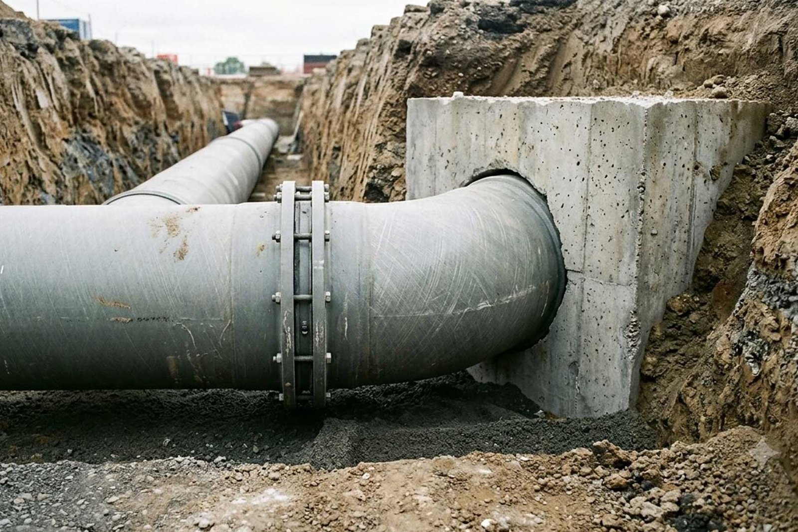
- Chambers and Transitions: When pipes enter valve chambers, tanks, or exposed sections, the load moves from soil support to concrete. If this detail is weak, it becomes a local failure point.
Below, we provide a short-type table of these thrust force locations.
| Pipeline Element | Thrust Direction | Main Restraint Concern |
|---|---|---|
| Horizontal bend | Along bend bisector | Soil bearing or restrained length |
| Vertical bend (up) | Upward force | Uplift and gravity block design |
| Tee / branch | Along branch axis | Branch thrust and local anchorage |
| Reducer | From larger to smaller diameter | Axial load imbalance |
| Dead end / closed valve | Axial along pipe | End thrust and anchorage |
| Chamber penetration | Into structure | Load transfer via collar or flange |
Which Pressure Controls Thrust Design in GRP/GRE Pipelines?
Thrust design in GRP/GRE pipelines starts with one decision: which pressure case actually governs the system. If that step is weak, block sizing and restrained length calculations lose reliability.
Why Nominal Pressure Is Not Enough for Design
Design cannot rely on pipe pressure class alone. Real pipelines see several pressure conditions:
- static operating pressure
- maximum operating pressure
- surge or water hammer
- hydrotest pressure
- pump trip and restart events
- fast valve closure
Hydrotest pressure can govern thrust design even though it is temporary. Surge pressure controls long transmission mains and pump stations where flow changes happen quickly.
Static vs Surge vs Hydrotest Pressure
Static pressure stays steady during normal operation. Surge rises and drops fast during flow changes. Hydrotest applies a controlled high pressure before commissioning, and this can exceed normal operating levels.
GRP/GRE pipes generally have lower pressure wave speed than steel or ductile iron. That can reduce surge intensity, but it does not remove the need for transient checks. In networks with branches, air valves, or staggered valve actions, local pressure spikes still occur.
- Takeaway: Before any thrust block or restrained length is sized, the full pressure envelope must be defined. Without it, thrust calculations and restraint design do not reflect real system conditions.
How Is Thrust Force Calculated at GRP/GRE Pipeline Fittings?
Thrust at fittings comes from internal pressure acting on changes in direction or pipe size. The idea is simple: pressure pushes, and fittings decide where that push goes.
Basic Equation
Where:
- F = thrust force
- P = internal pressure
- A = pipe internal area
This gives the starting point before geometry is considered.
1. Bends
At bends, the flow changes direction, so the pipe reacts with a force along the bend line. Horizontal bends push sideways. Vertical bends can lift or drop the pipe depending on orientation. A 45° bend produces more thrust than a small angle because the change in direction is larger.
2. Dead Ends
At dead ends, blind flanges, or closed valves, full pressure acts on the pipe face. The force has nowhere to spread, so it becomes a straight axial push. These points usually need firm anchoring.
3. Tees and Reducers
Tees push force into the branch side based on branch area. Reducers shift force from a larger pipe to a smaller one, which creates imbalance along the axis. These locations near pumps or chambers tend to see more variation in load.
What Data Do You Need Before Designing Thrust Restraint in GRP/GRE Pipelines?
Thrust restraint design depends on how well the input data reflects real hydraulic, soil, pipe, and site conditions. If any part is missing, the design usually shifts either too conservative or unsafe in practice.
● Hydraulic Data
This defines how much force the system produces. Pipe diameter, pressure class, operating and test pressure, surge values, and flow velocity all sit here. Pump and valve behaviour matters as well, especially for trips and fast closure cases.
● Soil Conditions
Soil controls how thrust gets resisted. Friction, bearing capacity, groundwater level, and trench depth change how much load the ground can take. Poor compaction or high water table usually reduces resistance.
● Pipe Details
Pipe size, stiffness class, weight, and water load set the geometry side of the problem. Axial capacity of restrained joints and manufacturer limits also matter. In GRE lines, temperature movement can start to influence restraint length.
● Site Limits
Space around bends, nearby utilities, trench stability, and dewatering needs decide what can actually be built. Chamber size and curing time before testing also affect execution.
The table below groups these inputs so engineers can quickly see what drives pressure, soil resistance, pipe capacity, and construction feasibility.
| Category | Main Input | Role |
|---|---|---|
| Pressure | MOP, surge | Thrust level |
| Soil | Friction, bearing | Resistance |
| Pipe | Size, stiffness | Load basis |
| Construction | Space, curing | Buildability |
How Do You Choose a Thrust Restraint Method in GRP/GRE Pipelines?
Choosing a restraint method is not a design preference. It depends on soil, space, and how forces can realistically be transferred on site.
When Does a Thrust Block Work?
Thrust blocks fit simple layouts where soil is strong and excavation space is available. They transfer load into the ground but need curing time and careful protection of the GRP/GRE pipe surface.
When Is Restrained Length Used?
Restrained length suits tight corridors or areas where concrete blocks are hard to build. It relies more on soil friction, so poor compaction or wet ground can reduce performance.
Consideration: Experimental friction studies of NW pipes show coated pipe friction depends on compaction, soil type, and moisture condition. This variability directly affects restrained length calculations.
When Do Anchor Systems Apply?
Anchor or thrust collar systems are used at chambers, tanks, or valve stations. Here, the load goes directly into reinforced concrete instead of soil.
When Is a Hybrid Solution Needed?
Hybrid systems appear in large pipelines or constrained sites where one method is not enough. It combines blocks, restraint, and structural anchorage depending on each location.
Anchor Block and Concrete Thrust Block Design for GRP/GRE Pipelines
Anchor and thrust blocks take pipe forces that soil alone cannot handle. The main concern is how the load moves from pipe to concrete, then into the ground.
PPI thrust restraint guidance shows that allowable soil bearing capacity commonly governs anchor block size more than concrete strength itself. Weak soils can require 2–5× larger bearing area.
Bearing Area Sizing of Thrust Blocks
The block spreads thrust into soil. Size depends on thrust force and soil strength. Weak or wet soil quickly increases block size, and sometimes pushes the design toward soil replacement or piles instead of larger concrete.
Sliding and Overturning Checks
Blocks can still move or rotate.
- Sliding depends on base friction with soil
- Overturning depends on where the thrust acts
- Valve chambers need proper structural design, not just mass concrete
Vertical Uplift and Gravity Blocks
Vertical bends can lift the pipe, especially in shallow cover or wet ground. Addition to the soil cover, we also need to add gravity blocks to make the connections tighter.
GRP/GRE Pipe Protection Inside Concrete
GRP/GRE pipes should not be in touch with hard concrete in a direct way. Wrapping or rubber layers help reduce stress points. Joints and fittings also need to stay accessible unless full restrictions are allowed.
Concrete Placement and Curing
Blocks need firm support and proper curing time. If testing starts early or dewatering is poor, the block can shift and lose capacity.Top of Form
How Does Load Move Through GRP/GRE Pipeline Restraint Systems?
Load transfer in GRP/GRE pipelines follows different paths depending on geometry and restraint type. Each path behaves differently in the field, so it needs to be checked separately during design.
Load Path 1: Fitting into Concrete Block and Soil
Used at bends, tees, reducers, and dead ends. The fitting pushes into the concrete block, and the block spreads that force into surrounding soil. Soil bearing capacity controls the block size. Weak or wet ground quickly increases concrete demand.
Load Path 2: Pipe Through Thrust Collar into Reinforced Concrete
Used at chamber entries, tanks, valve stations, and wet wells. Force travels along the pipe wall until it reaches a thrust collar or puddle flange. From there, it transfers into reinforced concrete and spreads through reinforcement. The pipe stays in axial load up to that interface.
Load Path 3: Fitting into Restrained Pipe and Soil Friction
Used where space is limited or blocks are not practical. The load moves through restrained joints and gradually dissipates along the pipeline through soil friction. Compaction quality, groundwater, and joint capacity control how well this path works.
Load Path 4: Valve or Equipment into Chamber Structure
Used for valves, pumps, strainers, and control units. Loads should only enter the chamber structure if it was designed for it. Otherwise, the chamber becomes a weak transfer point instead of a proper support.
Final Note: AWWA M45 design guidance shows thrust force increases with internal pressure, pipe diameter, and bend angle. Large diameter pipelines therefore require significantly larger restraint systems or hybrid solutions.
What Should Be Considered for GRP/GRE Pipe-Specific Design?
GRP/GRE pipes don’t behave like steel or ductile iron. The way they move, carry load, and react to soil changes the whole restraint approach.
Amiblu confirms GRP pipelines act as soil–structure systems where bedding and side support control deformation. Pipe stiffness alone is not sufficient for performance prediction.
- How does flexible pipe behavior change things?
These pipes move with the ground more than they resist it. So bedding, side support, and compaction end up controlling how the load is shared, not just the pipe itself. - What controls joint movement?
Joints only tolerate a limited amount of pull or push. If restraint forces build up too much, seals can start to lose tightness or joints can separate slightly.
EBAA restraint design tools show restrained joint systems are governed by allowable axial load per joint, which depends on gasket friction and mechanical locking geometry. Exceeding this value leads to joint separation before pipe failure. - Where do local stresses appear?
Small contact points matter. Hard concrete edges or uneven support can create stress spots on the pipe wall, which GRP/GRE doesn’t handle well. - How do temperature and pressure play a role?
Heat and internal pressure slowly shift the pipe length and shape. Over long runs, this movement adds up and needs to be considered in restraint layout. - Why check with the manufacturer?
Each system has its own limits. What works for steel doesn’t directly apply here, and that mismatch is where most design issues start.
Worked Example: Why Thrust Design Changes on Site
GRP/GRE thrust design can look fine in calculations but shift once real soil and groundwater conditions are considered. A DN 800 PN 10 line with a 45° bend is a usual case. U.S. Federal Highway Administration notes that governing pressure may increase when surge or test conditions are included, raising thrust demand. This forces a choice between a concrete block and restrained length.
In good soil, a compact block works. In weak or wet ground, the block becomes too large, so restrained length becomes more practical, though it depends on friction and compaction quality.
The decision usually follows site conditions, not initial cost.
EPC Workflow for Thrust Restraint Design in GRP/GRE Pipelines
In real EPC jobs, thrust restraint is not a clean sequence on paper. It is a chain of decisions that keeps adjusting as design meets site limits. What looks correct in design needs small corrections once soil, space, and construction methods are known.
- Collect Project Data
This matter begins with basic inputs from different sides. Hydraulic conditions, soil reports, pipe and fitting data, and even excavation limits all go into one place. Missing details here usually create changes later. - Define Pressure Envelope
Normal operating pressure is only part of the picture. Surge and hydrotest cases often push the design higher and control how much thrust actually develops in the system.
WSSC Water notes that transient surge events can exceed steady operating pressure depending on valve closure and system response. This makes surge a primary design case for thrust restraint, not a secondary check. - Calculate Thrust Forces
Each change in direction or size creates a force. Bends, tees, reducers, dead ends, valves, and chamber entries are checked one by one, since each behaves differently in practice. - Select Restraint Method
At this point, the design becomes site-driven. Some locations take thrust blocks, others rely on restrained length, and some need anchor blocks or thrust collars where structures are involved. - Check Pipe–Soil Interaction
This is where things often get adjusted. Joint limits, soil compaction, groundwater, and axial capacity all interact, and the assumed behavior on paper does not always match the trench. - Prepare Drawings and Schedules
The idea is translated into something site teams can follow. Block sizes, restrained lengths, chamber details, and installation notes are laid out clearly so nothing is left to interpretation. - Construction QA/QC
On site, execution matters more than theory. Excavation quality, compaction, pipe protection, concrete placement, reinforcement, and curing, all can affect how the system actually performs. - Hydrotest Readiness
Before testing starts, everything needs to be in place and stable. Restraints, curing time, and access points are checked again, since this is usually where hidden issues show up.
Common Mistakes in GRP/GRE Thrust Restraint Design
Most thrust restraint issues do not come from complex calculations. They usually come from simple assumptions carried too far into design or construction. The table below shows where these problems mainly appear and what usually prevents them.
| Common mistake | What goes wrong in practice | How to avoid it |
|---|---|---|
| Using only nominal pressure | Thrust is underestimated during surge or hydrotest | Always design for full pressure envelope |
| Copying standard thrust block details | Soil conditions are ignored | Use site-specific geotechnical data |
| Ignoring groundwater | Buoyancy reduces stability | Check water table and uplift effects |
| Assuming soil cohesion | Overestimation of soil resistance | Verify soil parameters from reports |
| Direct concrete contact on pipe | Local stress damage on GRP/GRE | Use separation layers or protection wrap |
| Covering couplings and gaskets | Maintenance and repair becomes impossible | Keep joints accessible in detailing |
| Ignoring joint movement limits | Leakage or joint separation | Check axial and angular limits |
| Using restrained length blindly | Axial capacity exceeded | Verify joint and pipe axial strength |
| Treating chambers as thrust blocks | Structure not designed for load transfer | Design chamber for actual thrust loads |
| Testing before curing | Block movement or failure | Respect curing time before hydrotest |
| Ignoring constructability | Design cannot be built in tight corridors | Review site access and sequencing early |
Small design gaps in restraint systems usually become field problems later, not calculation errors. A quick check against soil data, pressure cases, and constructability often prevents most of these issues before they reach construction stage.
What LineCore Pipes Group Provides
LineCore Pipes Group supports GRP/GRE water transmission projects from design to site execution, with focus on how thrust is handled in real field conditions. Here are just a few of where exactly can LineCore help the clients:
- Pipe and fitting selection based on project pressure, alignment, and installation limits
- Hydraulic checks including operating, surge, and hydrotest cases for thrust evaluation
- Restraint and anchor planning based on soil conditions, space, and site buildability
That’s why LineCore Pipes Group is your dedicated partner to support the EPC team in thrust restraint design alignment. It helps bridge the gap between design assumptions and real site conditions, so execution stays consistent with engineering intent.
about
The Author

Farshid Tavakoli is a seasoned professional in engineering and international trade. Holding degrees in Electrical Engineering, Mechatronics, and a Doctorate in Business Administration (DBA) from the University of Lyon, he also has a strong background in industrial automation and production line technologies.
For over 17 years, he has led an international trading company, gaining deep expertise in commercial solutions tailored to industrial needs. With more than 8 years of active involvement in infrastructure development, he specializes in the supply of electromechanical equipment for water and wastewater treatment plants and transfer projects.
Together with comapny expert team, he now provides consultancy and integrated solutions for sourcing and implementing complex infrastructure projects across the region.